Understanding and addressing common soil problems is crucial for maintaining a safe and secure work environment, particularly in industries that involve excavation, construction, or other activities that interact with the ground. In this comprehensive guide, we delve into the common soil problems outlined in OSHA guidelines, offering insights into the potential risks they pose and the recommended measures to mitigate them. By familiarizing yourself with these issues and implementing appropriate preventive measures, you can safeguard the well-being of workers and promote a culture of safety in your workplace.
Also Read: Temporary Construction Facilities (TCF) Inspection checklist

General
The terms soil and earth are commonly used in the excavation process to describe the naturally occurring materials uncovered on a project. Soil conditions vary from one site to the next. The soil may be loose or partially cemented, organic or inorganic. However, most soils can be referred to as a mixture or an accumulation of mineral grains that are not cemented together. An exception is hard rock, which remains firm after exposure to the elements.
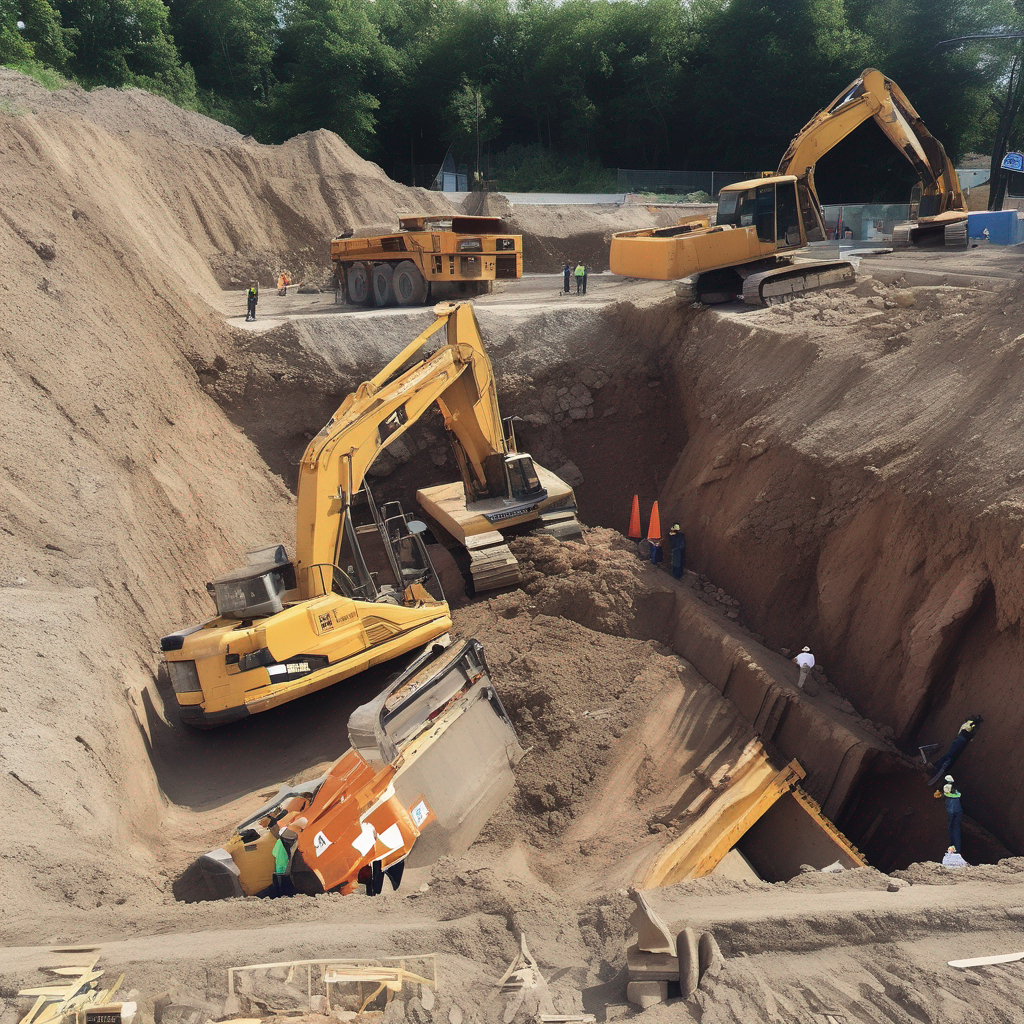
Soil failure is defined as the collapse of part or all of an excavation wall. The most common soil failure is typically described as an unexpected settlement, or cave-in, of an excavation. Soil sliding is the most common factor leading to soil failure.
Proper planning and supervision can avoid the unsafe working conditions caused by soil sliding. Unless such safety precautions have been implemented, sliding soil failure can occur in all types of excavations (including sloped trenches and excavations with braced trench boxes). See Figure 1.
Figure 1
Sliding Failure
Overview: Soil Mechanics
A number of stresses and deformations can occur in an open cut or trench. For example, increases or decreases in moisture content can adversely affect the stability of a trench or excavation. The following diagrams show some of the more frequently identified causes of trench failure.
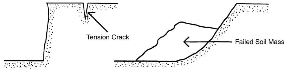
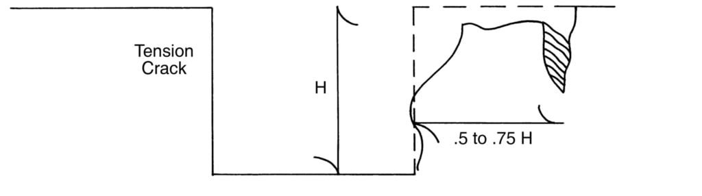
Tension cracks. Tension cracks usually form at a horizontal distance of one-half to three-quarters times the depth of the trench, measured from the top of the vertical face of the trench. See Figure 2 for additional details.
Figure 2
Tension Crack
Sliding or sluffing may occur as a result of tension cracks, as illustrated in Figure 3.
Figure 3
Sliding

Toppling. In addition to sliding, tension cracks can cause toppling. Toppling occurs when the trench’s vertical face shears along the tension crack line and topples into the excavation. See Figure 4.
Figure 4
Toppling

Subsidence and Bulging. An unsupported excavation can create an unbalanced stress in the soil, which, in turn, causes subsidence at the surface and bulging of the vertical face of the trench. If uncorrected, this condition can cause face failure and entrapment of workers in the trench. See Figure 5.
Figure 5
Subsidence and Bulging

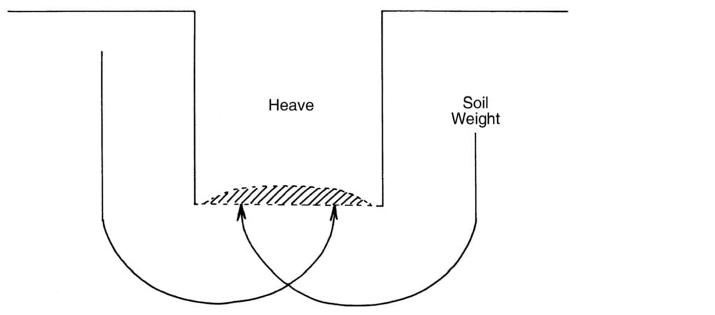
Heaving or squeezing Bottom heaving or squeezing is caused by the downward pressure created by the weight of adjoining soil. This pressure causes a bulge in the bottom of the cut, as illustrated in Figure 6. Heaving and squeezing can occur even when shoring or shielding has been properly installed.
Figure 6
Heaving or Squeezing
Boiling is evidenced by an upward water flow into the bottom of the cut. A high water table is one of the causes of boiling. Boiling produces a “quick” condition in the bottom of the cut and can occur even when shoring or trench boxes are used. See Figure 7.
Figure 7
Boiling

Unit Weight of soil refers to the weight of one unit of a particular soil. The weight of soil varies with type and moisture content. One cubic foot of soil can weigh from 110 pounds to 140 pounds or more, and one cubic meter (35.3 cubic feet) of soil can weigh more than 3,000 pounds.
A safe slope can be defined as the maximum angle of the edge wall or bank of an excavation at which sliding will not occur. The unique mixtures of the different types of soil (sand, clay, silt, and rock) necessitate different safe slopes from one excavation site to the next.
There are other complicating factors that can result in sliding soil failures. During an excavation, visibly different layers of soil may be uncovered. Each of those layers may call for different safe slopes. It is essential to plan your excavation
around the most gradual (rather than steepest) safe slope for all of the different soil types and layers encountered during the excavation.
Another complicating factor is that soil composition mixtures may vary significantly from one area of the project to another. During an excavation, as the soil composition changes, the safe slope for trench wall excavation also changes. Thus, across an excavation site, the slope of the bank may need to be different to provide a safe working environment.
Sliding and other modes of failure can also occur in soils that are not densely compacted. For example, a trench that is made close to a previously dug trench is very unstable. If uncompacted soil is discovered, the normal safe slope for dense soil will not be enough to prevent sliding. Bracing or further sloping may be necessary.
If cracks are observed in rocky types of soil, sliding has already occurred. These cracks should signal that a more gradual slope for excavation is needed because the rocky soil is very susceptible to slides and other types of failure.
Excavations that have been stable for long periods are also subject to sliding types of failure. After prolonged exposure to the elements, the moisture content in the soil may increase. This increase in moisture may be due to various causes, such as rainfall or a broken water line. The extra soil moisture tends to speed up sliding soil failures.
Determining the correct safe slope can be quite difficult for certain types of soil. The OSHA standard has developed a simple method of determining safe excavation bank slopes for different soil types. This method will be discussed in more detail in a later section of this document.
Soil failure can occur for any number of reasons. Factors that increase the chances of soil failure are:
- excessive vibration
- surface encumbrances
- weather conditions
Cave-ins and Protective Support Systems
Excavation workers are exposed to many hazards, but the chief hazard is danger of cave-ins. OSHA requires that in all excavations, employees exposed to potential cave-ins must be protected by sloping or benching the sides of the excavation, by supporting the sides of the excavation, or by placing a shield between the side of the excavation and the work area. Designing a protective system can be complex because of the number of factors involved—soil classification, depth of cut, water content of soil, changes due to weather and climate, or other operations in the vicinity. The standard, however, provides several different methods and approaches (four for sloping and four for shoring, including the use of shields) for designing protective systems that can be used to provide the required level of protection against cave-ins.
One method of ensuring the safety and health of workers in an excavation is to slope the sides to an angle not steeper than one and one-half horizontal to one vertical (34 degrees measured from the horizontal). These slopes must be excavated to form configurations that are in accordance with those for Type C soil . A slope of this grade or less is considered safe for any type of soil. (See Figure 8).
Figure 8
Type C Soil: Simple Slope Excavation

All simple slope excavations 20 feet (6.1 meters) or less in depth must have a maximum allowable slope of 1.5:1. A second design method, which can be applied for both sloping and shoring, involves using tabulated data, such as tables and charts, approved by a registered professional engineer. These data must be in writing and must include sufficient explanatory information to enable the user to make a selection, including the criteria for determining the selection and the limits on the use of the data. At least one copy of the information, including the identity of the registered professional engineer who approved the data, must be kept at the worksite during the construction of the protective system. Upon completion of the system, the data may be stored away from the job site, but a copy must be made available upon request to NCDOL. Contractors may also use a trench box or shield that is either designed or approved by a registered professional engineer or is based on tabulated data prepared or approved by a registered professional engineer. Timber, aluminum, or other suitable materials may also be used. OSHA standards permit the use of a trench shield (also known as a welder’s hut) as long as the protection it provides is equal to or greater than the protection that would be provided by the appropriate shoring system. (See Figure 9.)
Figure 9
Trench Shield

The standard does not require the installation and use of a protective system when an excavation is made entirely in stable rock or is less than 5 feet (1.52 meters) and a competent person has examined the ground and found no indication of a potential cave-in.
Vibrations
Any large, heavy movement near an excavation results in the vibration of the surrounding soil. This movement can result in soil failure. Moving machinery, nearby traffic, pile driving, and blasting all cause vibration in the surrounding soil.
Vibration-related soil failures can occur in all types of soil. However, certain types of soils are more susceptible to vibration failures than others. For example, sandy soils tolerate less vibration than clay soils.
Since actual soil conditions may be a mixture of more than one soil type, it is better to play it safe when planning the slope of an excavation. Figure 10 shows typical situations where vibrations can result in soil failure.
Figure 10
Two Examples of Vibration Failures

Surface Encumbrances
Heavy loads such as large equipment, heavy materials or large spoil piles can be too heavy for the soil to support, result- ing in a cave-in. These loads are referred to as surface encumbrances. They pose different types of dangers (see Figure 11). For example, large spoil piles may hide tension cracks that would otherwise signal that a sliding soil failure may occur.
Figure 11
Surface Encumbrances

Existing site features such as buildings, curbs, trees, utility poles, and other structures adjoining the excavation area may be considered types of surface encumbrances. These extra loads can place more stress on the sides of an excavation than the walls can safely carry. Shoring, bracing, underpinning or some combination of safety measures should be provided, as necessary, to protect workers and to prevent movement of the soil beneath the adjacent load.
In cases where space is limited and heavy loads must be located near an excavation, the trench walls must be braced or shored as needed to safely support this extra weight.
Weather Conditions
Weather is an important factor in determining soil conditions. More importantly, changing weather conditions may signal a change in the pressure exerted by the soil on the side walls of a trench.
Excess water from rain or melting snow interacts with the soil, increasing the pressure on the excavation and shoring systems. For instance, a rainstorm can turn a stable trench wall that requires only light bracing into a mass of loose soil that requires heavy bracing.
Freezing usually indicates a rather stable ground condition, unless the frost line is exceeded during excavation. The frost line phenomenon is depicted in Figure 12. If you excavate or shore frozen ground, be aware that another potential problem exists—thawing. A sudden thaw can be as dangerous as a rainstorm.
Figure 12
Region of Soil Freezing

Excessively dry conditions can also be dangerous. As moisture content decreases, some dry soils lose their ability to stick together. This lack of cohesion may result in a sliding type of soil failure. In many of the situations described above, dewatering or extra shoring may be required as necessary to ensure the safety of your workers. See Figures 16 and 17 in Part 2 for more information about dewatering.