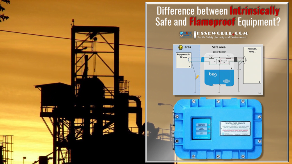
Hazardous areas such as oil refineries, paint shops, and chemical plants have a high potential for explosions. In such an area, a small spark is enough to cause an ignition. Since these hazardous explosions could occur even with special technologies in place, it is very important that during the designing of a factory, electrical apparatus should not be placed in these hazardous areas. (Intrinsically Safe and Flameproof Equipment )
Having said that, it is important to note that these locations require special equipment installed to protect workers and other people within the vicinity against any explosion eventualities. This especially makes equipment falls under two categories, namely:
- The intrinsically safe
- The flameproof
So in this article, you will be familiar with the Difference between Intrinsically Safe and Flameproof Equipment
First: Flameproof / Explosion proof equipment
The equipment is simply contained in a heavy protective enclosure, usually made of die-cast steel, occasionally plastic. If heat or sparks from faulty equipment within the enclosure ignite flammable gas present with it the resulting explosion is contained within the enclosure. In North America, metal conduits must be used for field wiring. In Europe and elsewhere suitably rated cable is connected directly to the equipment using certified flameproof cable glands.
Principles:
- It must be capable of withstanding explosions
- Servicing of these devices is only done by trained personnel and is done with proper tools
- They are heavier and bulkier
- Most commonly used metals are cast aluminium and steel
Limitations of the Explosion Proof Technology:
- The costs of stainless steel or aluminium used to make the enclosures are expensive
- When the atmosphere is very humid, problems may arise inside the enclosures due to condensation
- Due to the heavyweights of the enclosures, there may be complications during the installation of the system
- The mechanical integrity of the system is what determines the extent of the safety of this system. If an inspection has not been done on the set times, safety is compromised
- Implementations of any changes to the system are difficult to carry out
Advantage – simple to design the system, suitable for high power equipment
Disadvantage – equipment becomes extremely heavy & expensive; opening the enclosure while powered is not permitted
Second: Intrinsically Safe
This approach limits the energy available to the intrinsically safe (I.S.). equipment, usually less than 2 watts, by means of a galvanic or Zener barrier in such a way that under no circumstance will the equipment be able to generate sufficient heat or sparks to ignite flammable gases. Both the I.S. equipment and the Zener barrier must be certified ‘Intrinsically Safe’ by BASEEFA, SIRA, or a similar authority.

A Zener barrier is associated equipment that is installed in the safe area. It is designed to limit the amount of energy that could appear in an electrical circuit that passes through the hazardous area despite the connection before the barrier. A barrier consists of:
- Resistors to limit the current
- Zener diodes to limit the voltage
- Fuses to protect the components
As with any intrinsic safety equipment, the Zener barrier allows cables to short circuit to each other or to metallic parts connected to the ground without danger.
The Zener barrier interfacing mode differs from others as there is no galvanic isolation. Cables that pass through the hazardous area thus share common features with those of the safe area. This implies equipotential grounding.
Figure (1) illustrates intrinsic safety equipment (A) connected to a circuit (C) through a Zener barrier (B) that limits the current, the voltage, and the power. If a fault voltage occurs between the terminals (m) and (n), the Zener diode (protected by a fuse) limits the voltage that risks appearing in the hazardous area and the resistor limits the current to an acceptable value.
If a fault voltage occurs between the terminal (m) or (n) and the ground, the voltage of the wires (e) and (f) relative to the ground will not exceed Vz provided that the Zener barrier is correctly ground
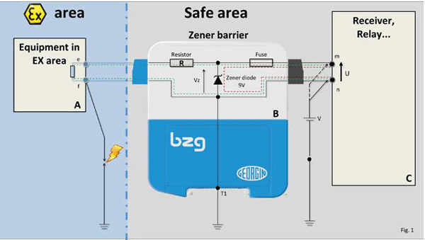
Current path in normal operation, U <= 9V
Current path in the overvoltage case, U <= 9V
The Zener diode becomes conducting The fuse protects the Zener diode from destruction
The Zener barrier permits wires (e) and (f) to be short-circuited without danger. However, if point (n) accidentally reaches a high potential relative to the ground, a ground fault at (f) risks causing a dangerous spark.
Advantage – considerably cheaper than comparable flameproof/explosion-proof equipment, no special cabling required. Live maintenance permitted, no need to shut down the plant
Disadvantage – only suitable for low power equipment e.g. sounders, beacons, and smoke detectors (which must be certified Intrinsically Safe)
Flame proof / Explosion proof (ATEX & ICEX equipment certified Exd & North American Class 1 Division 2 equipment)
i. The terms ‘explosion proof’ and ‘flameproof’ are largely interchangeable. Although there are some subtle differences, engineers and the market in general usually use both terms to mean the same thing, i.e. a piece of electrical equipment designed for use in a hazardous area by means of heavy-duty enclosure.
ii. The cabling of any system employing ATEX or ICEX Exd certified equipment e.g. E2S Ltd. BEX series sounders or GNEX series xenon beacon, must use suitably rated and mechanically protected cable. The cable must be terminated using Exd certified cable glands and junction boxes. The glands and junction boxes must be certified Exd by BASEEFA, SIRA, or similar recognized authority to the same level as the field equipment. ( read more about: Everything you need to know about the explosion )
Intrinsically Safe Equipment (ATEX & ICEX equipment certified Exia, Exib, Exic & North American Class 1 Div 1 equipment)
Here safety in hazardous areas is achieved by using a Zener barrier situated between the control panel and the device e.g. the E2S Ltd MiniAlarm sounders, or Apollo Orbis Series I.S. smoke detectors. The basic I.S. circuit is shown below:

The manufacturer of the I.S. device will specify the type of I.S. safety barrier.
Connection cabling requirements
i. Although there are few restrictions on the type of cable used in IS circuits all cables have inductance and capacitance, and hence energy storage capabilities, thus they can affect system safety. The capacitance and inductance values of a given cable should be readily available from the cable manufacturer. In addition, the capacitance and inductance values of the field-mounted devices such as IS sounders and smoke detectors must also be taken into account, again the values should be readily available from the manufacturer Consequently the system design imposes restrictions on the amount of each of these parameters. A great deal has been written on this subject but only rarely is there a serious limitation placed on the available cable.
ii. The cabling must conform to the following requirements
a. have protection from mechanical damage
b. have protection from chemical attack e.g. acids etc.
c. be securely fixed
d. have a minimum conductor size of 0.017mm2
e. must withstand 500V insulation test
f. circuit voltage must not exceed 60V
iii. The following types of cables can be used:
a. screened instrument cable
b. multi-core signal cable (e.g. telephone cable) subject to certain conditions relating to screening and earthing
c. multi-core miniature electric cables
d. conventional cables with conventional insulating sheaf e.g. PVC with a minimum insulation thickness of 0.3mm.
iii. There are no special requirements for junction boxes used in intrinsically safe circuits. However, they must be clearly identified as being part of an Intrinsically safe system
iv. Installation of cables used in intrinsically safe circuits:
The installation of IS devices and associated equipment must conform to IEC 60079-14
Cable trays, ducts, and conduits carrying intrinsically safe circuits should be separate from cable trays, ducts, etc. carrying any other cables. Note that in the U.K. I.E.T. wiring regulations prohibit electrical services e.g. power and lighting circuit cabling to be carried in the same conduit or duct as IS circuits.
Installation of cables used in intrinsically safe circuits
It is usually considered good practice to separate cable trays, ducts, and conduits carrying intrinsically safe circuits from trays and ducts carrying any other cables, e.g. telephones & computer cables. I.E.E. wiring regulations prohibit electrical services, e.g. power and lighting to be carried in the same conduit.
( Know What is Meaning of %LEL , %UEL , PID )